Design Documents
ThermLink provides the following design documents for each system we sell:
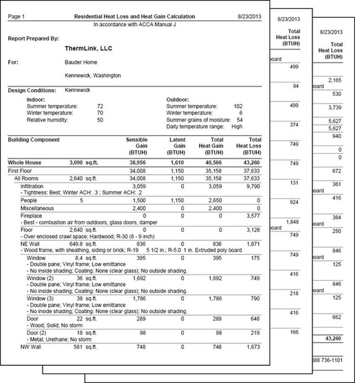
Manual J Heat Loss / Heat Gain Calculation
The first design component that ThermLink provides is a heat loss / heat gain calculation in accordance with ACCA Manual J. This critical step is based on the house plans and becomes the basis for the system design.
The first design component that ThermLink provides is a heat loss / heat gain calculation in accordance with ACCA Manual J. This critical step is based on the house plans and becomes the basis for the system design.
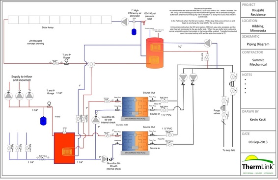
Piping & Equipment Diagram
Each ThermLink system includes a complete piping and equipment layout diagram. These provide the HVAC contractor with a solid diagram to follow during installation.
Each ThermLink system includes a complete piping and equipment layout diagram. These provide the HVAC contractor with a solid diagram to follow during installation.
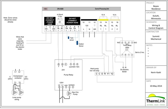
Wiring & Controls Schematic
Wiring & controls are often one of the most time-consuming parts of the installation so ThermLink provides a complete diagram for the contractor to follow.
Wiring & controls are often one of the most time-consuming parts of the installation so ThermLink provides a complete diagram for the contractor to follow.
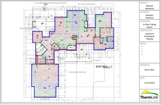
In-Floor Tubing Layout
For hydronic systems a complete drawing of the layout of the in-floor tubing is provided. This shows each hydronic zone, the tube spacing, and the locations of the manifolds.
For hydronic systems a complete drawing of the layout of the in-floor tubing is provided. This shows each hydronic zone, the tube spacing, and the locations of the manifolds.
